Voltage in parallel circuits

Lesson details
Learning outcome
I can describe the rule for voltages in a parallel circuit.
Key learning points
- A voltmeter is connected to each side of a cell, battery or component.
- Voltage (or potential difference) is measured in volts (V).
- The voltage across a cell or battery measures the strength with which it can ‘push’ current around a circuit.
- The voltage across a component in an electric circuit measures the size of ‘push’ that is moving current through it.
- The voltage across each branch of a parallel circuit is the same as the voltage across the cell or battery.
Keywords
Voltmeter - A voltmeter is a device that is connected in parallel and measures the voltage supplied by a cell or battery or across a component.
Voltage - Voltage is a measure of the 'push' from a cell or battery that moves charge around a circuit.
Potential difference - Potential difference is a more formal term for voltage; they can be used interchangeably.
Parallel circuit - A parallel circuit is an electric circuit with more than one complete loop from one end of a cell or battery to the other end.
Common misconception
Voltage in a parallel circuit is shared out between each branch of the circuit.
Provide opportunity for pupils to measure voltage across each branch of a range of parallel circuits to give evidence for the correct rule.
Teacher tip
Pupils should understand a rule for voltage in parallel circuits in order to understand how current flows through each branch in a parallel circuit. This rule is covered in this lesson and ‘Loops of a parallel circuit’. These two lessons should be completed before 'Currents in a parallel circuit'.
Equipment
For each group: voltmeter, connecting wires (×8), 1.5 V cell (×3), bulb, buzzer, motor and resistor.
Content guidance
Risk assessment required - equipment
Supervision
Adult supervision required
Licence
Lesson video
Loading...
Prior knowledge starter quiz
6 Questions
Q1.Which of the following statements about series circuits is correct?
Q2.Which of the following statements about parallel circuits is correct?
Q3.Which of the following statements about the junctions in a parallel circuit are correct?
Q4.When building a parallel circuit, which of the following statements describes the most effective method to use?
Q5.Which of the following statements about circuit diagrams is correct?
Q6.A real parallel circuit is made using a circuit diagram for reference.
Which of the following statements is correct?
Assessment exit quiz
6 Questions
Q1.Which of the following devices measures the 'push' that a cell or a battery gives to current?
Q2.Which of the following statements correctly describe how voltmeters should be connected?
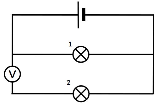
Q3.What will happen to the lamps in the circuit shown when the circuit is connected?
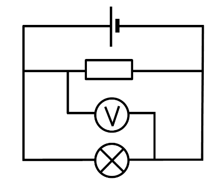
Q4.What is the voltage across the lamp if the voltage of the battery is 1.5 V?
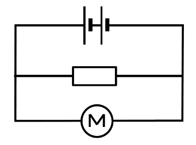
Q5.What is the voltage across the battery of two cells if the voltage across the resistor is 2.0 V and across the motor is 3.0 V?
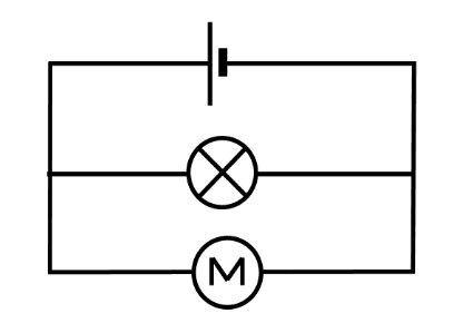
Q6.What is the voltmeter measuring?
To help you plan your 9 science lesson on: Voltage in parallel circuits, download all teaching resources for free and adapt to suit your pupils' needs...
To help you plan your 9 science lesson on: Voltage in parallel circuits, download all teaching resources for free and adapt to suit your pupils' needs.
The starter quiz will activate and check your pupils' prior knowledge, with versions available both with and without answers in PDF format.
We use learning cycles to break down learning into key concepts or ideas linked to the learning outcome. Each learning cycle features explanations with checks for understanding and practice tasks with feedback. All of this is found in our slide decks, ready for you to download and edit. The practice tasks are also available as printable worksheets and some lessons have additional materials with extra material you might need for teaching the lesson.
The assessment exit quiz will test your pupils' understanding of the key learning points.
Our video is a tool for planning, showing how other teachers might teach the lesson, offering helpful tips, modelled explanations and inspiration for your own delivery in the classroom. Plus, you can set it as homework or revision for pupils and keep their learning on track by sharing an online pupil version of this lesson.
Explore more key stage 3 science lessons from the Resistance and parallel circuits unit, dive into the full secondary science curriculum, or learn more about lesson planning.